")
The heart of nearly every internal combustion engine, the crankshaft and connecting rod assembly, represents a fascinating interplay of mechanical engineering principles. This mechanism, often referred to as a slider-crank system, is responsible for the fundamental task of converting the linear, reciprocating motion of the pistons into the rotational motion required to drive a vehicle or power machinery. While the concept seems straightforward, the actual dynamics involved are remarkably complex, involving rapidly changing forces, accelerations, and stresses. Understanding these dynamics is absolutely critical for designing engines that are powerful, efficient, durable, and smooth-running. Frankly speaking, overlooking the subtleties of crankshaft and connecting rod behavior can lead to issues ranging from excessive vibration and noise to catastrophic component failure. This analysis delves into the technical aspects of this crucial system, exploring the kinematics, forces, stresses, and design considerations that engineers grapple with daily. We'll examine how factors like geometry, mass distribution, operating speed, and combustion pressure intricately influence the behavior of these core engine components, ultimately dictating the engine's overall performance and character. It's a journey into the core mechanics that make our modern engines possible.
The Fundamental Kinematics: Translating Reciprocation into Rotation
At its core, the relationship between the piston, connecting rod, and crankshaft is governed by kinematics – the study of motion without considering the forces causing it. The piston moves up and down within the cylinder in a linear fashion. The crankshaft rotates about its central axis. The connecting rod acts as the crucial link, with its small end attached to the piston pin (or gudgeon pin) and its big end encircling the crankshaft's crankpin. As the crankshaft rotates, the crankpin traces a circular path, pulling and pushing the connecting rod, which in turn forces the piston up and down. However, an interesting aspect arises due to the finite length of the connecting rod. If the rod were infinitely long, the piston's motion would be perfectly sinusoidal. But because it has a finite length, the piston's velocity and acceleration profiles become more complex. The piston actually travels slightly faster near the top dead center (TDC) position compared to the bottom dead center (BDC) position for a given crank angle change, and its acceleration curve is not a pure sine wave. This deviation from simple harmonic motion is directly influenced by the ratio of the connecting rod length (L) to the crank radius (R), often called the L/R ratio. A smaller L/R ratio (shorter rod or longer stroke) exaggerates this non-sinusoidal motion, leading to higher peak accelerations and potentially increased secondary vibrations. Understanding piston position, velocity, and acceleration as functions of crank angle is the first step in analyzing the dynamic forces within the engine, as these kinematic properties directly determine the inertial forces generated by the moving components.
Inertial Forces and Their Impact
Whenever masses accelerate or decelerate, inertial forces arise, acting in the opposite direction of the acceleration. In an engine, the piston assembly (piston, rings, pin) and the connecting rod possess significant mass, and they undergo rapid changes in velocity throughout each cycle. This generates substantial inertial forces that must be managed. These forces can be broadly categorized into primary and secondary forces. Primary inertial forces occur at the same frequency as crankshaft rotation and are primarily due to the fundamental reciprocating motion. Secondary inertial forces occur at twice the crankshaft frequency and arise because of the non-sinusoidal piston motion caused by the finite connecting rod length, as discussed earlier. These inertial forces act along the cylinder axis, pushing and pulling on the crankshaft through the connecting rod. Furthermore, the connecting rod itself has both reciprocating mass (associated with the small end moving with the piston) and rotating mass (associated with the big end moving with the crankpin). The inertial force from the rotating mass contributes to crankshaft bending and requires counterbalancing. The combined effect of these reciprocating and rotating inertial forces contributes significantly to engine vibration, puts cyclic stress on bearings and the engine block, and can limit the maximum safe operating speed. Have you ever wondered why some engines feel inherently smoother than others? Often, it comes down to how effectively these inherent inertial forces are managed through design and balancing strategies.
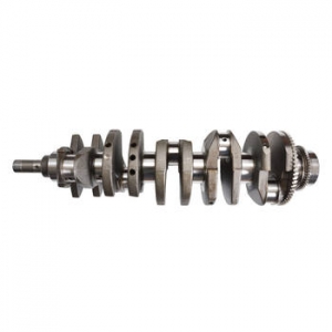
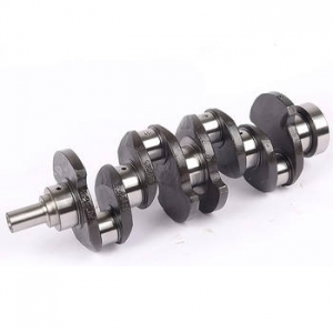
Balancing Acts: Counterweights and Their Role
Given the significant inertial forces generated, engine designers employ various strategies to counteract them, primarily through the use of crankshaft counterweights. These carefully shaped masses are integrated into the crankshaft, typically opposite the crankpins. Their main purpose is to offset the inertial forces generated by the rotating mass of the connecting rod's big end and the crankpin itself. By placing mass opposite the crankpin, the centrifugal force generated by the counterweight counteracts the centrifugal force of the crankpin and associated rotating mass, leading to smoother rotation and reduced load on the main bearings. Additionally, counterweights are often designed to counteract a *portion* of the reciprocating inertial forces (primary forces). Fully balancing primary reciprocating forces with crankshaft counterweights alone is often not feasible or desirable, as it can introduce shaking forces in the horizontal plane (for a vertical engine). The degree of balancing is a critical design choice, often specific to the engine configuration (inline-4, V6, V8, boxer, etc.). For instance, inline-four engines have inherent secondary inertial force imbalances that cannot be easily cancelled by crankshaft counterweights alone, often necessitating separate balance shafts rotating at twice the engine speed. It's worth noting that the design and placement of crankshaft counterweights involve complex calculations considering the mass of the piston assembly, the connecting rod's mass distribution, and the desired level of balance across the operating speed range. Achieving optimal balance is a delicate compromise between reducing vibration and minimizing overall crankshaft mass and complexity.
Connecting Rod Motion: More Than Just a Link
While often visualized as a simple rigid link, the connecting rod experiences a surprisingly complex state of motion and loading. It doesn't just move up and down or rotate; it undergoes complex planar motion, simultaneously oscillating and translating. This complex motion means different parts of the rod experience different accelerations, leading to internal inertial forces within the rod itself. Beyond its own inertia, the connecting rod acts as the conduit for transmitting the immense force generated by gas pressure during the power stroke from the piston to the crankshaft. This subjects the rod to enormous compressive stress. Conversely, during the exhaust and intake strokes, and particularly at high engine speeds during the transition around TDC, the rod experiences significant tensile forces due to the inertia of the piston assembly resisting the change in direction. Furthermore, the angularity of the connecting rod means that the force transmitted is not perfectly aligned with the rod's axis, inducing bending stresses, especially significant near the middle of the rod's length. To withstand these demanding, cyclic loads – compression, tension, and bending – connecting rod design and material selection are paramount. Common designs include the I-beam and H-beam cross-sections, optimized to provide high strength and stiffness, particularly against buckling under compression, while minimizing mass. Materials range from forged steel in mainstream applications to high-strength alloys and even titanium or metal matrix composites in high-performance and racing engines where reducing reciprocating mass is crucial for achieving higher speeds and better dynamic response.
Gas Pressure Forces and Torque Generation
The entire purpose of the crankshaft and connecting rod mechanism in an engine is, fundamentally, to convert the force generated by expanding gases during combustion into useful rotational work, or torque. When combustion occurs, extremely high pressure is exerted on the piston crown. This force, often reaching thousands of pounds or tens of thousands of Newtons, pushes the piston down. The connecting rod transmits this force from the piston pin to the crankpin. However, the force transmitted to the crankpin doesn't directly translate into torque equally at all times. The effective torque generated depends on two main factors: the magnitude of the force transmitted along the connecting rod and the effective lever arm distance at which this force acts on the crankshaft. This lever arm is determined by the instantaneous crank angle and the connecting rod angle. Maximum torque is typically generated not when the gas pressure is highest (which usually occurs shortly after TDC), but rather when the combination of substantial gas pressure and a favorable crank angle (typically somewhere between 60 and 90 degrees after TDC) produces the largest turning moment. It's crucial to distinguish between indicated torque (the theoretical torque generated based on gas pressure) and brake torque (the actual usable torque available at the flywheel, after accounting for frictional losses within the engine). Analyzing the pressure-volume (P-V) diagram for the engine cycle provides insight into the work done per cycle, which is directly related to the torque produced. Optimizing combustion timing and chamber design aims to maximize the effective pressure acting over the most advantageous crank angles for torque production.
Bearing Loads and Lubrication Dynamics
The interfaces where the connecting rod meets the piston pin (small end bearing) and the crankshaft (big end bearing), along with the crankshaft's own main bearings supporting it in the engine block, are subjected to some of the most severe loading conditions within the engine. The forces acting on these bearings are a dynamic combination of the gas pressure forces transmitted from the piston and the inertial forces generated by the moving masses. These forces change dramatically in both magnitude and direction throughout each engine cycle, and they increase significantly with engine speed and load. For example, the big end bearing experiences a force that rotates around the bearing surface as the crankshaft turns, driven by both downward gas pressure forces and outward inertial forces. Preventing metal-to-metal contact under these extreme, rapidly varying loads relies on the principle of hydrodynamic lubrication. A continuous supply of pressurized lubricating oil is fed to these bearings. The relative motion between the journal (crankpin or piston pin) and the bearing surface, combined with the oil's viscosity, generates a high-pressure oil film within the small clearance space. This pressurized wedge of oil physically separates the moving metal surfaces, drastically reducing friction and wear. Why is maintaining adequate oil pressure and flow absolutely critical? Because if this oil film breaks down, even momentarily, rapid wear and catastrophic bearing seizure can occur. Bearing materials (like Babbitt metal or aluminum-tin alloys) are chosen for their conformability, embeddability (ability to absorb small debris), and fatigue strength, while design features like oil grooves and precise clearances are engineered to promote effective oil film formation and heat dissipation.
Torsional Vibration and Crankshaft Design
Beyond the bending and bearing loads, the crankshaft is also susceptible to torsional vibration. Think of the crankshaft as a long, elastic shaft. Each time a cylinder fires, it delivers a powerful torque pulse to the crankshaft. These intermittent pulses, combined with the inertial torques from the accelerating pistons and connecting rods, excite the crankshaft, causing it to twist and untwist along its length. This is torsional vibration. While some degree of twisting is unavoidable, if the frequency of these exciting torque pulses matches one of the crankshaft's natural torsional frequencies, resonance can occur. Resonant torsional vibration can lead to dramatically amplified twisting angles and stresses within the crankshaft, potentially causing fatigue failure, often near changes in cross-section or oil holes. Factors influencing torsional vibration characteristics include the engine's firing order (which determines the sequence and timing of torque pulses), the number of cylinders, the crankshaft's length and stiffness (material properties and geometry), and the inertia of components attached to the crankshaft, particularly the flywheel at one end and the pulley/damper assembly at the other. To mitigate harmful torsional vibrations, especially in engines with long crankshafts or uneven firing intervals, engineers often incorporate a torsional damper (also known as a harmonic balancer) on the free end of the crankshaft. These devices, typically consisting of an inertia ring bonded to a hub via an elastomeric element or viscous fluid, are designed to absorb or counteract torsional vibration energy at critical frequencies, thereby protecting the crankshaft and ensuring smoother operation. In my experience, accurately modeling and controlling torsional dynamics is particularly vital in high-output engines and large diesel applications.
Advanced Considerations and Material Science
While the fundamental principles of crankshaft and connecting rod dynamics remain constant, the pursuit of higher performance, better fuel efficiency, and increased durability continually pushes the boundaries of design and materials science. Treating these components as perfectly rigid bodies is a useful simplification for basic analysis, but in reality, both the crankshaft and connecting rod deform elastically under the immense loads they experience. Modern engineering heavily relies on sophisticated tools like Finite Element Analysis (FEA) to model these deformations, predict stress concentrations, and optimize component shapes for maximum strength and minimum weight. This allows designers to strategically add material where stresses are highest and remove it where it's not needed, leading to lighter and more responsive engine internals. The choice of materials plays an equally critical role. While forged steel remains common for its strength and cost-effectiveness, high-performance applications increasingly utilize advanced alloys, powdered metals (allowing complex shapes), or even lightweight materials like titanium for connecting rods or specialized steel alloys for crankshafts capable of handling extreme stresses. Manufacturing processes have also advanced significantly, with precision machining, advanced forging techniques, and surface treatments (like shot peening or nitriding) enhancing fatigue life and wear resistance. Furthermore, specialized coatings are often applied to piston pins, crankpins, and bearing surfaces to further reduce friction and improve longevity under demanding conditions. These advanced considerations are essential for pushing the envelope in modern engine design, meeting stringent emissions regulations, and satisfying consumer demands for power and refinement.
Practical Applications and Our Solutions
A thorough understanding of crankshaft and connecting rod dynamics is not just an academic exercise; it has profound practical implications across the entire lifecycle of an engine. During the initial design phase, this knowledge informs crucial decisions about engine geometry (stroke, bore, rod length), material selection, counterweight design, and bearing specifications. It allows engineers to predict potential vibration issues, estimate component stresses, and optimize the design for specific goals, whether it's maximizing power output for a racing engine, ensuring long-term durability for a heavy-duty truck engine, or achieving exceptional smoothness and fuel efficiency for a passenger car. During performance tuning, understanding how changes in factors like engine speed or combustion characteristics affect the dynamic loads helps tuners push performance limits safely. In diagnostics and failure analysis, recognizing the signatures of problems related to these dynamics – specific vibration frequencies, characteristic wear patterns on bearings, or typical fatigue fracture locations – is essential for identifying root causes. This complex field is precisely where our company provides significant value. We offer specialized engineering services and advanced simulation software focused on analyzing and optimizing the dynamic behavior of engine components like crankshafts and connecting rods. Our solutions enable engineers to perform detailed kinematic and dynamic force analyses, predict bearing loads, evaluate torsional vibration characteristics, and assess component stresses with high fidelity. By leveraging our expertise and tools, design teams can make more informed decisions, accelerate development cycles, troubleshoot complex issues, and ultimately create more robust, efficient, and high-performing engines. Have you considered how a deeper dynamic analysis could resolve persistent vibration issues or unlock further performance potential in your engine designs?
In conclusion, the seemingly simple mechanism converting linear to rotary motion within an engine is governed by a complex and fascinating set of dynamic principles. The technical analysis of crankshaft and connecting rod dynamics reveals a world of interacting forces – gas pressure, primary and secondary inertia, bending moments, and torsional loads – all acting cyclically on components operating under extreme conditions. From the fundamental kinematics dictating piston motion to the critical role of lubrication in preventing bearing failure, and the sophisticated methods used for balancing and vibration control, every aspect demands careful engineering consideration. Material science, advanced simulation techniques like FEA, and precise manufacturing are constantly evolving to meet the ever-increasing demands placed on these core engine parts. Effectively managing these dynamics is not just about performance; it's fundamental to engine longevity, efficiency, and refinement. The continuous effort to understand and optimize the intricate dance between the crankshaft and connecting rod remains a cornerstone of internal combustion engine development, ensuring these powerhouses continue to evolve. How might future material or design innovations further refine this critical mechanical relationship?
For more detailed information, please visit our official website: Crankshaft dynamics